Regulator Standards
CE EN 250 is the most widely recognised standard for the testing and marking of open-circuit self-contained compressed-air scuba diving breathing apparatus.
The standard contains limits on inhalation and exhalation pressures and overall work of breathing. It specifies the following, under test conditions of a breathing rate of 62.5 litres (2.2 cu ft) per minute and an ambient pressure of 6 bars (600 kPa):
- Work of breathing: <3.0 joules per litre
- Peak respiratory pressure: ±25 mbar (±2.5 kPa) (inhalation or exhalation)
- Inhalation work of breathing: <0.3 joule per litre
- Pressure spikes with no measurable positive work of breathing: <10 mbar (1 kPa)
- Pressure spikes with measurable positive work of breathing: <5 mbar (0.5 kPa)
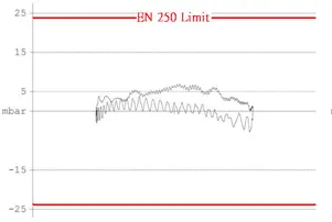
The primary measurement is in "joules per litre." Testing is carried out using a breathing simulator. The regulator is connected to a "test diver" (mannequin) and lowered to depth. An artificial lung inhales and exhales gas at a prescribed rate while breathing resistance is measured. Measurements are taken at various depths, temperatures, and supply pressures. The test data is then analysed to construct a work-of-breathing (WOB) curve. Ideally, the curve should be evenly distributed close to the 0.0 line, with the smallest possible area under both the inhalation (lower) and exhalation (upper) curves.
Although a regulator that meets the limits above will deliver adequate air, this represents only the minimum standard (3.0 joules/litre at 6 bar). High-performance regulators achieve an impedance value of less than 0.8 joules/litre at the same depth. When comparing WOB curves, a tighter, more closely grouped curve is better. The EN 250 standard does not apply to ice water, as its minimum working temperature is 10°C.
The following shows manufacturers' WOB results at a depth of 50m (6 bar), with a cylinder pressure of 300 bar, water temperature of 2°–4°C, and a breathing rate of 25 breaths per minute.
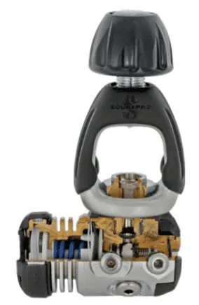
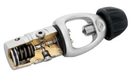
Common First Stage Regulator Designs
The operating principle behind all common regulator designs is essentially the same: a spring forces open the orifice between the high-pressure chamber and the intermediate-pressure chamber. When the intermediate pressure rises sufficiently to overcome the spring force, the orifice is sealed and high-pressure air stops flowing into the intermediate-pressure chamber. This means that when a first stage regulator fails, it fails open — delivering a continuous flow of air — rather than cutting off the air supply (fail-safe).
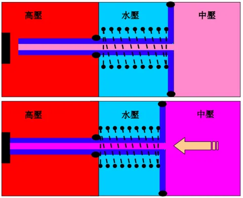
Downstream Piston Regulator
The downstream piston design uses piston movement to open and close the inlet from the high-pressure chamber. The spring tension pulls the piston open to allow air into the intermediate-pressure chamber. A hole in the piston rod directs air into the piston cylinder; when the pressure inside the cylinder builds enough to overcome the spring force, the piston is pushed back and the inlet is closed.
Opening force = Spring tension + Ambient pressure × Piston area + High pressure × High-pressure seat area
Closing force = Intermediate pressure × Piston area
Advantages of the Downstream Piston Regulator
This classic design has few internal parts, making it inexpensive, highly reliable, and low-maintenance — the preferred choice for rental equipment at dive shops.
Disadvantages of the Downstream Piston Regulator
As the name implies, the piston and the high-pressure inlet are on the same axis, so piston movement must work against cylinder pressure. As a result, the intermediate-pressure output fluctuates with the remaining cylinder pressure — a difference that becomes noticeably pronounced toward the end of a dive. In addition, piston-type regulators require an environmental port that allows seawater to contact the piston for depth-pressure compensation; thorough rinsing is essential after each use.
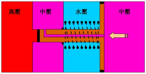
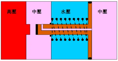
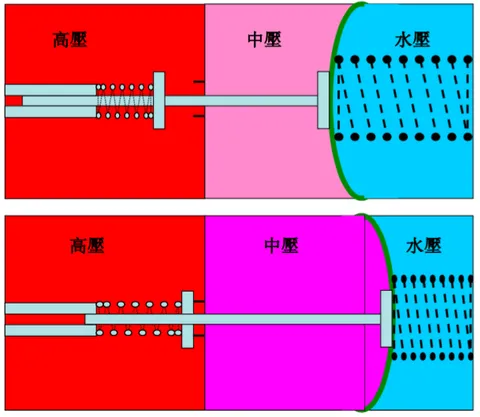
Balanced Piston Regulator
The balanced piston regulator also uses piston movement to open and close the high-pressure inlet, but the position of the high-pressure seat and the direction of airflow have been redesigned. The spring still pulls the piston open to admit air into the intermediate-pressure chamber, but here the top of the piston rod has an opening that leads directly into the intermediate-pressure chamber (piston cylinder). When the pressure inside the cylinder builds enough to overcome the spring force, the piston is pushed back and the inlet is closed.
Opening force = Spring tension + Ambient pressure × Piston area
Closing force = Intermediate pressure × Piston area
Advantages of the Balanced Piston Regulator
Compared with other designs, the balanced piston regulator delivers the highest airflow. Its specially designed high-pressure chamber ensures a consistently stable intermediate-pressure output that is completely unaffected by cylinder pressure. A lighter composite piston enables more responsive action. The regulator continues to deliver a steady flow of air even at low cylinder pressures, allowing a fatigued diver to breathe more easily during ascent or decompression stops. The balanced piston design is the top choice for demanding recreational divers and professionals alike, and performs equally well in both warm and cold water.
Disadvantages of the Balanced Piston Regulator
Piston-type regulators require an environmental port that allows seawater to contact the piston for depth-pressure compensation. Although some manufacturers have improved on this by fitting a dual O-ring on the piston to enhance environmental sealing, thorough rinsing after use remains necessary. Currently, only one regulator achieves complete environmental isolation by means of silicone oil filling and a fully sealed chamber, enabling operation even in polluted water.
Diaphragm First Stage Regulator
The diaphragm first stage regulator uses a membrane (diaphragm) positioned between the intermediate-pressure chamber and the external environment, with the intermediate-pressure spring on the ambient side. As intermediate pressure rises, the diaphragm flexes inward, counteracting both the spring force and ambient pressure. This drives a push-rod upward, blocking the orifice between the high-pressure chamber and the intermediate-pressure chamber. The diaphragm design delivers stable intermediate-pressure output with a fast response, making it well suited for use with high-pressure cylinders. Some designs incorporate an additional diaphragm over the environmental port for even more thorough environmental sealing — particularly useful when working in contaminated or silty water.
Opening force = Spring tension + Ambient pressure × Diaphragm area
Closing force = Intermediate pressure × Diaphragm area + High-pressure spring tension + (High pressure − Intermediate pressure) × High-pressure seat area
Advantages of the Diaphragm First Stage Regulator
The diaphragm first stage regulator is fully environmentally sealed, preventing water from entering the internal mechanism. Intermediate pressure can be adjusted simply by changing the external intermediate-pressure spring tension.
Disadvantages of the Diaphragm First Stage Regulator
The diaphragm first stage regulator has a comparatively complex construction. Its sensitive moving metal components should be kept away from extremely cold environments, or a cold-water kit should be installed to improve performance. Intermediate pressure may rise slightly as cylinder pressure drops.